
Saturday, April 2, 2011
Widget running with Ubuntu 10.10
Can't believe I haven't posted in almost a year (been pretty busy...) but finally got the Widget a couple month ago from George (great job to George, Alex, Loftur, and the rest of the team!) Took me a few days of hacking and searching thru the mailing list, but finally got ghpSDR3 running with the Widget. Still trying to figure out how to fix the SI570 offset... but for now a great start.

Sunday, April 25, 2010
PCF8574 Lives!
Well after spending a couple hours beating on it, turns out I had done the address jumpers backwards on the board. So solder the dip switch as normal with "On" at the top, then flip it over to address it. Here's a quick and dirty addressing table:
PCF8574AT:
The soldering is a bit messy as I had removed several components (including the PCF8574) while troubleshooting the addressing problem. However here are the pics of MoboControl and the board connected to a fan.


PCF8574AT:
A2 | A1 | A0 | Address |
0 | 0 | 0 | 56 (38h) |
0 | 0 | 1 | 57 (39h) |
0 | 1 | 0 | 58 (3Ah) |
0 | 1 | 1 | 59 (3Bh) |
1 | 0 | 0 | 60 (3Ch) |
1 | 0 | 1 | 61 (3Dh) |
1 | 1 | 0 | 62 (3Eh) |
1 | 1 | 1 | 63 (3Fh) |
The soldering is a bit messy as I had removed several components (including the PCF8574) while troubleshooting the addressing problem. However here are the pics of MoboControl and the board connected to a fan.

Messily soldered board...

...and we have lift off!
Saturday, April 24, 2010
I2C PCF8574 Board and Parts are in!
Just got back from some fishing... and had a nice surprise waiting for me. Both the boards I had ordered and my ULN2803s I had ordered from Hong Kong arrived. Since my wife badly wants to go to a game tomorrow, she's cooking dinner so I can play. :)


Top of the board

Bottom of the board
Sunday, March 21, 2010
SR63ng Board Built
Finished buttoning together my SR63ng board from George, who did a great job designing the board and assembling the kit. Also was able to hit quite a few beacons today on WSPR with it, so it's working great!


SR63ng Top

SR63ng Bottom
Sunday, March 14, 2010
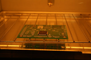
Reflow Oven
So I finally got a chance to do a bit more practice this weekend with my reflow controller and modified toaster oven. First of all I highly recommend the Black and Decker Infrawave ovens, they heat fast with quick response which is perfect. The second thing I recommend is making sure you understand the heating profile of the solder paste you use. My first test was a disaster as it turns out I had the wrong profile for the stuff I had gotten locally. After a bit of trial and error, I found a profile that works out well for me. Attached a few pics below, the 100pin chip was SO much easier with the oven. I did have several solder bridges since there was a bit too much paste, but the solder braid/wick cleaned it up nicely. Chip worked too! Though until I cooked it as my board has a bug somewhere, but that's a whole other story...
I think I'm now ready for the SDR-Widget and it's 144pin chip!

I think I'm now ready for the SDR-Widget and it's 144pin chip!

Applied the paste
Placed the chup pretty close to where it needs to go

Board baking away for 2.5 minutes

Final result, several blobs, but perfectly lined up! A lot easier than eyeing it the old way...
Monday, March 1, 2010
SMD Reflow soldering and other updates
Been working on a little project the last few days that I hope will be done this week so I can post some pics. I modified an Infrawave oven to a computer controlled reflow controller so I can start doing SMT parts using solder paste in the oven. With any luck this won't be a total disaster :) Hope to post some pics in a couple days when it's done, and maybe even do my first reflow!
Also got some other good news, got my 2nd motherboard 4.3 kit from Art today, as well as confirmation of my shipping SoftRock 6.3NG board from George. Will be having some fun soon with these!
Also got some other good news, got my 2nd motherboard 4.3 kit from Art today, as well as confirmation of my shipping SoftRock 6.3NG board from George. Will be having some fun soon with these!
Monday, February 15, 2010
Oops... Rookie mistake!
Ok, so I try to be the first to admit when I make a mistake... and here's a good one. I've been having weird issues on transmit with my Softrock/Mobo where if I transmit towards the center frequency with digital modes, all is well. However if I transmit in either direction, audio is off it seemed. I decided to play with WSPR tonight, and could decode stations fine, but no one could hear me and I only was heard once or twice a few weeks ago on 30m. Perplexed I start fiddling with my other rig to see where my output was, as it's a nice straight line it's easy to see what's happening, and noticed it was a lot lower than it should be. Tried three or four times, reset my Mobo settings, tried PowerSDR 1.12 and 1.9... even reloaded the Delta44 drivers. Mind you to complicate matters, around the same time I got my new SR 6.3 board and the MoBo kit, I rebuilt my ham PC, so I had quite a few variables here for troubleshooting before someone goes "Ah! The issue is pretty obvious!!!"
Finally the light went off when I was trying to see if it was the LCD offset for PowerSDR and the Mobo that was screwing it up. I was off in the exact opposite direction than where I wanted to be. Turns out when I put the Mobo and SoftRock into the case, I had used polarized connectors (good), however when I put them in, the connector was loose, so the pins came out of the plug (bad). As you can probably guess by now, I had the L/R reversed which is why if I was off center at all, I would get no where as my digital mode audio was reversed. Like magic, everything seems to work correctly now that they are lined up... OOPS!
On a side note, I ordered one of George's SR6.3 NG boards, can't wait to get it! Also ordered the SI570 chip a couple weeks ago that came in. I hope to blog about my assembly experiences here with what I find.
Tuesday, January 19, 2010
PowerSDR seems to be working!
For some reason I couldn't hit any beacons in JT65, however I realized for some reason my sound card was outputting strangely to PowerSDR when I monitored it from a 2nd PC. THe JT65A transmission was duplicated all over the waterfall. I dropped the output to mono and it fixed it, weird. Though mono breaks PSK31. Good news is I finally hit some beacons for the first time for JT65A and PSK31. Starting to feel better that this is working correctly after some of the issues I've gone thru. I also like the new PowerSDR 1.19.3.15 from SV1EIA which seems to be pretty stable on my system.

PSK31 and JT65 monitors
VE3ODZ-1 (FN03ha) Heard KB1MTS(FN42) on 3576.50 KHz -10dB at 01:47:00Z using JT65A
N9DSJ-2 (En52ti) Heard KB1MTS(FN42) on 3576.50 KHz -14dB at 01:47:00Z using JT65A

New PowerSDR
Friday, January 15, 2010
Finally have transmit working!
Well after working with Alex and a couple other's (thanks for the help!), I finally got the calibrate and transmit working with the Motherboard. I was seeing 8.6v on the adjust line input on the LM317 adjustable regulator. After doing a lot of trouleshooting, I found that due to all the adjustments I was making with the heatsink, one of the pins had broken and was making poor contact. Once I resoldered the pin, all the problems went away. My next challenge is to get it mounted into a case :)
Hopefully make my first contacts this weekend...
Hopefully make my first contacts this weekend...
Saturday, December 12, 2009
Logic Analyzers are your friend...
Just wanted to post about how handy a logic analyzer can be. Last Saturday spent several hours trying to debug why the SPI output to a HT1632 LED controller was working on my Arduino but couldn't get it working with my PIC. After spending a few minutes with the logic analzyer and decoding the bits coming up from the PC that were true SPI, I then connected it to the Arduino and noticed the output there was NOT SPI per the LED documentation but just simple bit banging. This also identified my ouput was noisey and not correctly switching the bits states to low. After sorting out the output settings on the PIC and switching the port to the correct output mode, I can now finally communicate with the LED controller. Definitely recommend the USB SX module... good price and great features (including 1wire, SPI and I2C decoding.)


Friday, December 4, 2009
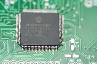
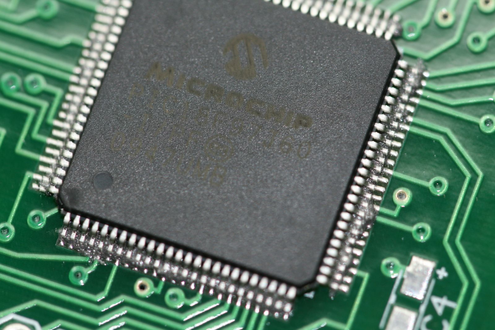
Hardest soldering job of my life so far...
Feeling pretty good right now, just finished soldering one of the hardest devices I have ever done so far... A Microchip PIC18F97J60 100pin TQFP surface mount PIC. Used the solder wick method, and only issue I had was one pin near the bottom shifted a bit due to too much pressure with the solder wick. However was able to move it over carefully with a needle and the PIC fired up and is running my program. Now whether I find one of the ports dead 6mos from now is another story... The pins are about the size if the "I" in the word "LIBERTY" on a penny.


Thursday, December 3, 2009
Watch out for P20 and K1!
Just a heads up for those putting the boards together... I hope this will save someone else's sanity :-) Make sure there are jumpers on both P20, and K1 (pin 1 and pin 2.) P20 enables the 12v side to enable receive and transmit. K1 controls transmit, so if pin 1 and pin 2 are open (not jumpered), it will instantly get stuck in transmit. After a couple of hours of frustration, I remembered this the hard way...
Subscribe to:
Posts (Atom)